
 Deutsch
Design and function
The bladder accumulator consists of a seamless, high strength steel pressure vessel. An elastomeric bladder assembled inside the vessel ensures that the vessel is divided into gas and fluid compartments. The bladder is filled with nitrogen up to the pre-set gas pressure p0 using the gas filler valve. If the fluid is pressed into the accumulator, the gas in the bladder is compressed, thereby increasing its pressure. The volume of gas is reduced and the fluid can flow into the accumulator on the fluid side. As soon as the pressure on the fluid side falls below that of the gas pressure, the fluid empties from the accumulator. The base valve on the fluid side prevents the bladder from being destroyed when the accumulator is almost full of gas.
Designation – Example of order

| 1: Type of accumulator BS bladder accumulator |
| 2: Nominal volume (litres) |
| 3: Max. permissible operating pressure |
| 4: Bladder materials E - ECO (Hydrin) -32°C to +115°C NT - TT NBR (low temperature) -28°C to +070°C N - NBR -15°C to +100°C B - ITR (Butyl) -15°C to +120°C V - FKM (Viton) -20°C to +140°C |
| 5: Fluid suply 0 - G 1/2" 1 - G 3/4" 2 - G 1 1/4" 3 - G 2" 4 - M30 x 1,5" 5 - M40 x 1,5" 6 - M50 x 1,5" 7 - VF flange inlet |
| 6: Accumulator material A - C steel, primed B - C steel, interior coated with plastic C- C steel, interior chemnically nickel plated T - low temperature steel R - stainless steel (e. g. 1.4571) |
| 7: Fluid supply-material A - C steel T - low temperature steel C- stainless steel (e. g. 1.4301) F - stainless steel (e. g. 1.4571) |
| 8: Gas precharge pressure p0 (bar) at 20 °C |
| 9: Acceptance test codes CE Directive 2014/68/EU |
| other on request |
Dimensions bladder accumulator
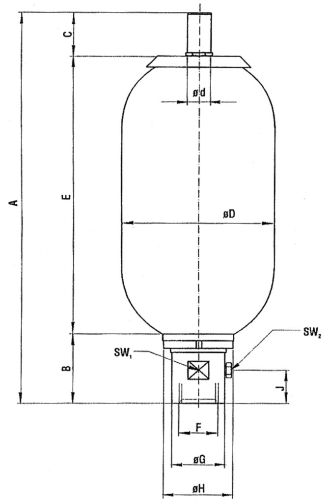
| Typ BLADDER ACCUMULATOR | gas vol. Vo (l) | MWP P (bar) | weight in kg | Q max (l/min) | A mm | B mm | C mm | ØD mm | Ød mm | E mm | F Zoll | ØG mm | ØH mm | SW 1 mm | SW 2 mm | J mm |
|---|---|---|---|---|---|---|---|---|---|---|---|---|---|---|---|---|
| BS 0,2-350/... | 0,17 | 350 | 1,7 | 150 | 265 | 39 | 26 | 56 | 16 | 200 | G ½ | 27 | 38 | 24 | ||
| BS 0,5-350/... | 0,60 | 350 | 2,5 | 240 | 248 | 52 | 22 | 90 | 16 | 174 | G ¾ | 36 | 50 | 32 | ||
| BS 1,0-350/... | 1,00 | 350 | 5,0 | 240 | 312 | 52 | 57 | 114 | 22 | 203 | G ¾ | 36 | 50 | 32 | ||
| BS 1,6-350/... | 1,60 | 350 | 7,0 | 240 | 395 | 52 | 27 | 114 | 16 | 316 | G ¾ | 36 | 50 | 32 | ||
| BS 2,5-350/... | 2,40 | 350 | 10,0 | 450 | 532 | 66 | 57 | 114 | 22 | 409 | G 1¼ | 53 | 67 | 50 | ||
| BS 4,0-350/... | 3,70 | 350 | 16,0 | 450 | 407 | 66 | 57 | 168 | 22 | 284 | G 1¼ | 53 | 67 | 50 | ||
| BS 5,0-350/... | 5,00 | 350 | 17,0 | 450 | 881 | 66 | 57 | 114 | 22 | 785 | G 1¼ | 53 | 67 | 50 | ||
| BS 6,0-350/... | 6,00 | 350 | 20,8 | 450 | 550 | 66 | 57 | 168 | 22 | 427 | G 1¼ | 53 | 67 | 50 | ||
| BS 10-350/...-L | 10,00 | 350 | 28,0 | 450 | 807 | 66 | 57 | 168 | 22 | 684 | G 1¼ | 53 | 67 | 50 | ||
| BS 10-330/...-K | 9,20 | 330 | 32,0 | 900 | 565 | 101 | 57 | 221 | 22 | 407 | G 2 | 76 | 101 | 71 | 19 | 48 |
| BS 12-330/... | 11,20 | 330 | 35,0 | 900 | 664 | 101 | 57 | 221 | 22 | 506 | G 2 | 76 | 101 | 71 | 19 | 48 |
| BS 20-330/... | 18,10 | 330 | 53,0 | 900 | 874 | 101 | 57 | 221 | 22 | 716 | G 2 | 76 | 101 | 71 | 19 | 48 |
| BS 24-330/... | 22,50 | 330 | 61,0 | 900 | 1016 | 101 | 57 | 221 | 22 | 858 | G 2 | 76 | 101 | 71 | 19 | 48 |
| BS 32-330/... | 33,40 | 330 | 85,0 | 900 | 1400 | 101 | 57 | 221 | 22 | 1242 | G 2 | 76 | 101 | 71 | 19 | 48 |
| BS 50-330/... | 48,70 | 330 | 123,0 | 900 | 1927 | 101 | 66 | 221 | 50 | 1760 | G 2 | 76 | 101 | 71 | 19 | 48 |
manufactoring tolerances are not considered
Characteristics
Installation position: Preferably vertically (liquid connection downwards) to horizontal, depending upon application. For the assembly of the filling and testing set an area of 200 mm is to be released above the accumulator.
Attachment: The accumulators are to be fastened according to size and weight. For the safe attachment we recommend HST-fastening parts, how clamps and bracket.
Allowable operating temperatur: -15 °C bis +100°C
Charging gas: Use nitrogen only.
Oxygen or compressed air means danger of explosion!
Fluids: Hydraulic oil, other fluids on request.
