
 Deutsch
TECHNICAL DATA DIAPHRAGM ACCUMULATOR
Design
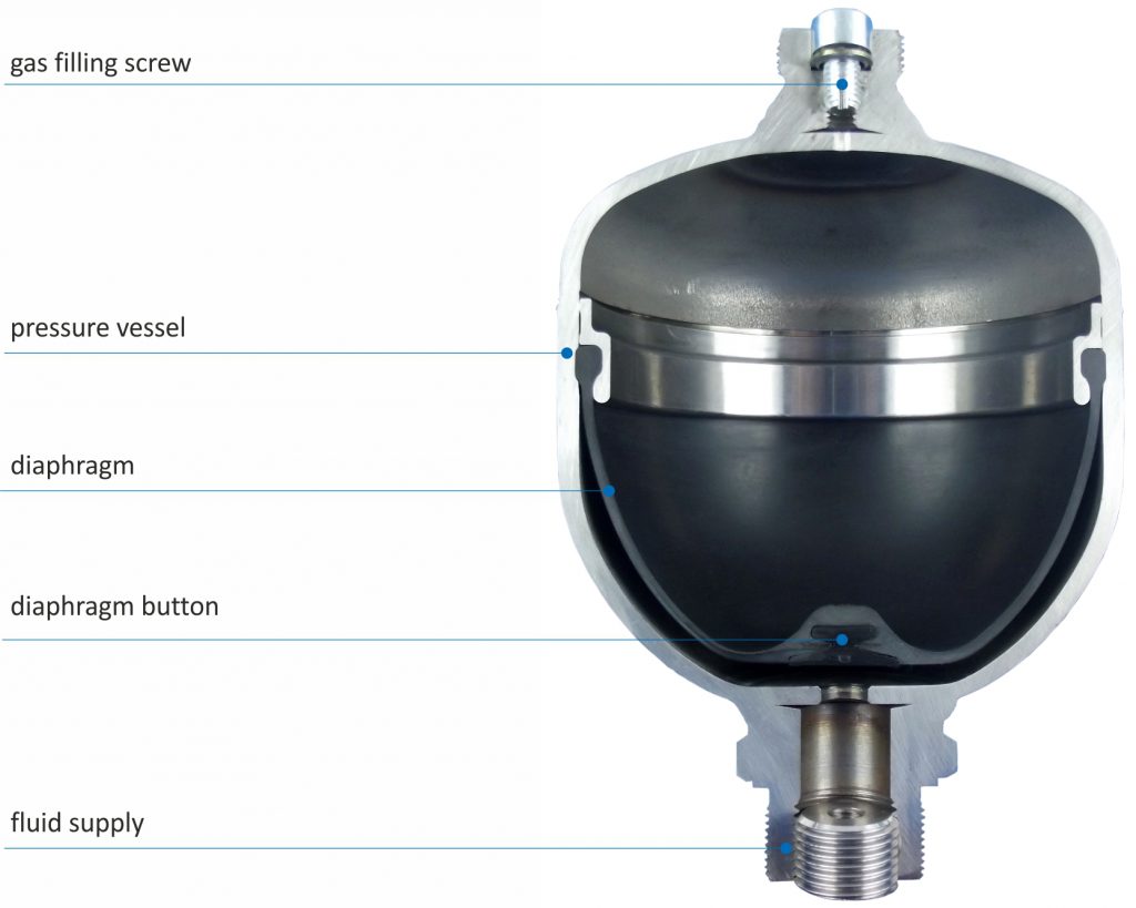
The diaphragm accumulator consists of a welded pressure chamber on the oil side of which a connection tube is welded. The separation of the gas and the fluid is carried out by a diaphragm inserted in advance. There is a diaphragm button in the bottom of the diaphragm to prevent the diaphragm completely from destruction when the vessel is discharged. The diaphragm accumulator can be refilled by means of a gas filling screw or can be closed so that it is inseparable on the gas side. The fluid supply is available in different versions.
Replacement of the diaphragm is not possible!
Designation – Example of order

| 1: Accumulator type MS diaphragm accumulator |
| 2: Nominal volume (Liter) |
| 3: Max. permissible operating pressure |
| 4: Design 1 gas can be refilled 2 gas cannot be refilled |
| 5: Diaphragm material N - NBR (zulässiger Temperaturbereich - 10°C bis + 80°C) E - ECO (Hydrin) (zulässiger Temperaturbereich - 40°C bis + 80°C) B - IIR (Butyl) (zulässiger Temperaturbereich - 15°C bis + 80°C) V - FKM (Viton) (zulässiger Temperaturbereich - 20°C bis + 80°C) |
| 6: Fluid supply shape (see table) |
| 7: Precharge pressure p0 (bar) at 20°C |
| 8: Accumulator material N - C-Stahl R - Edelstahl (z. B. 1.4571) T - Stahl für Temperaturen bis -40°C R/N - Edelstahl / C-Stahl |
| 9: Acceptance test - codes CE Directive 2014/68/EU |
| Pleace for temperatures about + 80°C consultation |
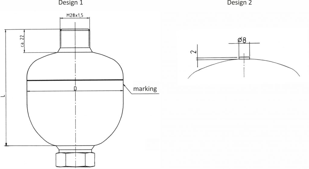
Dimensions Diaphragm accumulator, welded construction
Diaphragm not exchangeable!
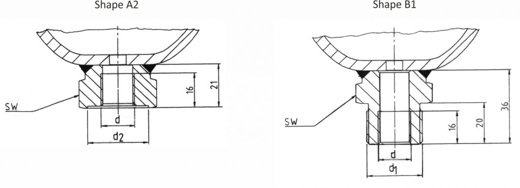
Fluid supplies
Technical Data Diaphragm accumulator – standard steel
0,075 – 3,5 litres / 80 – 350 bar
| Diaphragm Accumulator Standard Steel Type | nominal volume litres | operating pressure P (bar) | perm. pressure ratio P2 : P0 | mass kg | volume flow Q (l/min) | L mm | Ø D mm | Ø d1 mm | Ø d Zoll | Ø d2 mm | SW mm | connec- tion form |
|---|---|---|---|---|---|---|---|---|---|---|---|---|
| MS 0,075 | 0,075 | 250 | 8 : 1 | 0,7 | 35 | 90 | 64 | G ½ | 29 | 32 | A2 | |
| MS 0,16 | 0,16 | 250 | 8 : 1 | 0,9 | 35 | 101 | 74 | G ½ | 29 | 32 | A2 | |
| MS 0,25 | 0,25 | 210 | 8 : 1 | 1,1 | 35 | 107 | 84 | G ½ | 29 | 32 | A2 | |
| MS 0,32 | 0,32 | 210 | 8 : 1 | 1,3 | 80 | 116 | 93 | G ½ | 29 | 32 | A2 | |
| MS 0,32 | 0,32 | 330 | 8 : 1 | 1,6 | 80 | 118 | 95 | G ½ | 29 | 32 | A2 | |
| MS 0,50 | 0,5 | 210 | 8 : 1 | 1,8 | 80 | 128 | 105 | M33x1,5 | G ½ | 29 | 41 | B1 |
| MS 0,50 | 0,5 | 330 | 8 : 1 | 2,4 | 80 | 136 | 110 | M33x1,5 | G ½ | 34 | 41 | B1 |
| MS 0,60 | 0,6 | 330 | 4 : 1 | 2,7 | 80 | 148 | 110 | M33x1,5 | G ½ | 34 | 41 | B1 |
| MS 0,75 | 0,75 | 150 | 8 : 1 | 2,1 | 80 | 140 | 117 | M33x1,5 | G ½ | 34 | 41 | B1 |
| MS 0,75 | 0,75 | 210 | 8 : 1 | 2,8 | 80 | 144 | 121 | M33x1,5 | G ½ | 34 | 41 | B1 |
| MS 0,75 | 0,75 | 330 | 8 : 1 | 3,5 | 80 | 148 | 125 | M33x1,5 | G ½ | 34 | 41 | B1 |
| MS 1,00 | 1,0 | 210 | 8 : 1 | 3,6 | 80 | 155 | 136 | M33x1,5 | G ½ | 34 | 41 | B1 |
| MS 1,00 | 1,0 | 250 | 8 : 1 | 3,6 | 80 | 155 | 136 | M33x1,5 | G ½ | 34 | 41 | B1 |
| MS 1,00 | 1,0 | 330 | 4 : 1 | 4,2 | 80 | 175 | 125 | M33x1,5 | G ½ | 34 | 41 | B1 |
| MS 1,40 | 1,4 | 140 | 8 : 1 | 5,2 | 80 | 178 | 150 | M33x1,5 | G ½ | 34 | 41 | B1 |
| MS 1,40 | 1,4 | 210 | 8 : 1 | 5,2 | 80 | 178 | 150 | M33x1,5 | G ½ | 34 | 41 | B1 |
| MS 1,40 | 1,4 | 250 | 8 : 1 | 5,2 | 80 | 178 | 150 | M33x1,5 | G ½ | 34 | 41 | B1 |
| MS 1,40 | 1,4 | 350 | 8 : 1 | 7,5 | 80 | 176 | 156 | M33x1,5 | G ½ | 34 | 41 | B1 |
| MS 2,00 | 2,0 | 100 | 8 : 1 | 5,5 | 140 | 192 | 163 | M33x1,5 | G ½ | 34 | 41 | B1 |
| MS 2,00 | 2,0 | 210 | 8 : 1 | 6,6 | 140 | 196 | 166 | M33x1,5 | G ½ | 34 | 41 | B1 |
| MS 2,00 | 2,0 | 250 | 8 : 1 | 7,5 | 140 | 200 | 170 | M33x1,5 | G ½ | 34 | 41 | B1 |
| MS 2,20 | 2,2 | 80 | 8 : 1 | 5,7 | 140 | 208 | 163 | M33x1,5 | G ½ | 34 | 41 | B1 |
| MS 2,80 | 2,8 | 210 | 4 : 1 | 8,2 | 140 | 248 | 166 | M33x1,5 | G ½ | 34 | 41 | B1 |
| MS 2,80 | 2,8 | 250 | 4 : 1 | 10,0 | 140 | 248 | 170 | M45x1,5 | G ¾ | 44 | 46 | B1 |
| MS 3,50 | 3,5 | 250 | 4 : 1 | 11,6 | 140 | 285 | 170 | M45x1,5 | G ¾ | 44 | 46 | B1 |
| MS 3,50 | 3,5 | 350 | 4 : 1 | 18,0 | 140 | 295 | 180 | M45x1,5 | G ¾ | 44 | 46 | B1 |
Technical Data Diaphragm accumulator – stainless steel
0,075 – 4,0 litres / 100 – 210 bar
| Diaphragm Accumulator Stainless Steel Type | nominal volume ltr. | operating pression P (bar) | perm. pressure ration P2 : P0 | mass kg | volume flow Q (l/min) | L mm | Ø D mm | Ø d1 mm | Ø d Zoll | Ø d2 mm | SW mm | connec- tion form |
|---|---|---|---|---|---|---|---|---|---|---|---|---|
| MS 0,075 | 0,075 | 200 | 8 : 1 | 0,7 | 35 | 90 | 64 | G ½ | 29 | 32 | A2 | |
| MS 0,16 | 0,16 | 180 | 8 : 1 | 0,9 | 35 | 101 | 74 | G ½ | 29 | 32 | A2 | |
| MS 0,25 | 0,25 | 160 | 8 : 1 | 1,1 | 35 | 107 | 84 | G ½ | 29 | 32 | A2 | |
| MS 0,32 | 0,32 | 160 | 8 : 1 | 1,3 | 80 | 116 | 93 | G ½ | 29 | 32 | A2 | |
| MS 0,50 | 0,5 | 150 | 8 : 1 | 1,7 | 80 | 130 | 105 | M33x1,5 | G ½ | 29 | 41 | B1 |
| MS 0,75 | 0,75 | 140 | 8 : 1 | 2,8 | 80 | 144 | 121 | M33x1,5 | G ½ | 34 | 41 | B1 |
| MS 0,75 | 0,75 | 210 | 8 : 1 | 3,5 | 80 | 148 | 125 | M33x1,5 | G ½ | 34 | 41 | B1 |
| MS 1,00 | 1,0 | 150 | 8 : 1 | 3,6 | 80 | 171 | 121 | M33x1,5 | G ½ | 34 | 41 | B1 |
| MS 1,40 | 1,4 | 150 | 8 : 1 | 5,2 | 80 | 178 | 150 | M33x1,5 | G ½ | 34 | 41 | B1 |
| MS 2,00 | 2,0 | 100 | 8 : 1 | 5,5 | 140 | 192 | 163 | M33x1,5 | G ½ | 34 | 41 | B1 |
| MS 2,80 | 2,8 | 100 | 4 : 1 | 6,0 | 140 | 244 | 163 | M33x1,5 | G ½ | 34 | 41 | B1 |
| MS 4,00 | 4,0 | 100 | 4 : 1 | 7,5 | 140 | 377 | 163 | M45x1,5 | G ½ | 46 | 46 | B1 |
Characteristics
Installation position: as desired
Permissible operating temperature: -10°C bis +80°C (other temperatures on request)
Charging gas: Use nitrogen only! Oxygen or compressed air means danger of explosion!
Fluids: hydraulic oil (other fluids on request)
Instructions for mounting, maintenance and repair
According to the provided operating conditions the diaphragm accumulators hould be charged at the charging pressure required in the place of installation.
When charging gas use nitrogen only! Oxygen means danger of explosion.
The diaphragm accumulators can be screwed directly on the piping. When using a fluid connection with external thread, the accumulator can be fastened in threaded holes. In case of strong vibrations the accumulator should be protected against loosening. For this we recommend the HST-clamp straps. In the vicinity of the diaphragm accumulator a discharge and shut-off valve and a safetyvalve against excess pressure have to be provided in the hydraulic system. The maintenance of the accumulator is limited to the control of the gas pressure necessary for the respective function. Furthermore, we recommend to check the tight fit of the fastening of the accumulator and the pipe connections. Repair and restoring work of the accumulator are strictly prohibited, neither mechanical machining nor welding, soldering or other heat treatment.
